HEART-LUNG MACHINES – SOME THOUGHTS ABOUT PUMP CONFIGURATION AND DESIGN.
By Collin Green
Colin G. Green, Copenhagen, Denmark. ([email protected])
I was recently chatting with an overseas perfusionist who sent me a photo of his pediatric CPB circuit set-up. He was particularly pleased with his low priming volume which was due to thoughtful design and tubing positioning: He positioned his venous/cardiotomy reservoir close to the table and about 20 cm lower than the patient’s right atrium giving him a relatively short venous line. He applied a touch of vacuum to the reservoir to assist his venous drainage. So everything looked good apart from his long sucker lines, both from the patient to the pumps and especially from the pumps to the higher reservoir, and his longer reservoir outlet to pump and oxygenator, and arterial line from pump to patient.. His machine was a conventional “4 in a row” modular pump configuration.
This started a discussion’ initiated by myself, on the merits and de-merits of conventional horizontal “3/4/5 in a row” modular pump machines. Admittedly there are machines today where the arterial pump can be re-positioned closer to the table and sometimes higher but to the best of my knowledge sucker and cardioplegia pumps tend to stay on the machine base. We both agreed that in principal it would be advantageous to have multi-positionable pumps to allow even more optimal circuit design . As far as I know there have only been two machines in recent years that have had multi-pump positioning flexibility – the Maquet HL 30 and the Medtronic Performer.
Neither of these seem to have caught on and there could be many reasons for this , both technically and commercially. The thought has crossed my mind that maybe they were too unconventional perhaps confirming that perfusionists generally are traditionalists and don’t like change. However they both allowed sucker lines to come in straight from the table and the oxygenator and arterial pump to be positioned higher in relation to patient and table. Maybe they weren’t that popular because they were primarily “stand-up and run” machines ! Todays perfusionists are used to sitting comfortably even though this means bending and stretching to access circuit components and hardware.
Now if we look back into history it’s interesting to note that the early machines from the late 1950’s did not have modular blood pumps. It was before their time. In fact the machine that performed the first successful cardiopulmonary bypass in 1953, the Gibbon machine, was a “stand-up and run” machine with pumps and oxygenator on the top surface. Below are examples of 4 machines from that period.
The first two are pictured above and on the left is the Gibbon Mark 2 machine with the vertical screen oxygenator. On the right is the machine as modified by Dr John Kirklin at the Mayo Clinic.
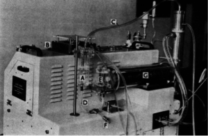
Above is the Guys-Ross machine with a Kay-Cross rotating disc oxygenator (C) with a venous reservoir (E). The arterial pump was on the side beneath the vertical stainless heat exchanger. There was one suction pump (B) on the top surface with a suction chamber (A). I did my first perfusions at Guys Hospital in London, England with this machine in 1962. Venous drainage was by gravity, no vacuum , into the venous reservoir. There was a drainage height of about 30 cm with generally no drainage problems.
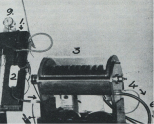
Interestingly the Kay-Cross disc oxygenator was inspired by an early disc oxygenator developed by Dr. Viking Bjoerk in Stockholm, Sweden in 1948. Below is this oxygenator which consisted of forty 13 cm diameter stainless discs in groups of 4 that oxygenated blood flows of up to 1100 ml/min. Dr. Bjoerk used this oxygenator for cerebral perfusion during occlusion of the vena cavae.
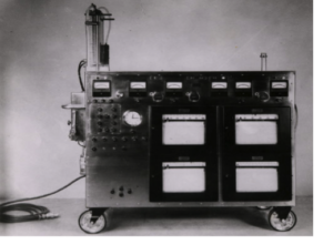
The Kay-Cross oxygenator was made in Cleveland, Ohio by Pemco Inc. and below is a photo of another “stand up and run” machine. This one made by Pemco with the disc oxygenator.
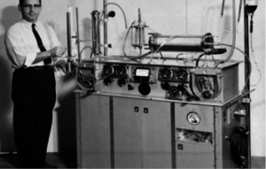
Again, oxygenator, pumps and heat exchanger on top of the machine at table level.
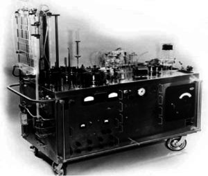
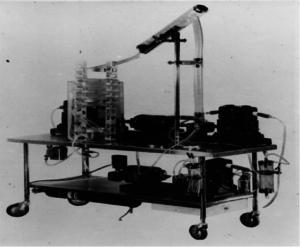
Lastly, one more “stand-up and run” machine. This time made in Copenhagen, Denmark by Polystan. This machine was designed to be used with one of the first disposable, pre-sterilzed bubble oxygenators, also made by Polystan. The first clinical with this machine was in Copenhagen on the 22nd of February 1957.
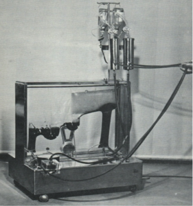
The arterial pump was on the left-hand side on top of the base cabinet. There were 3 vacuum chambers for 3 individual sucker lines. Vacuum to these chambers was supplied from a vacuum pump in the machine base and the amount of vacuum was controllable for each chamber. If you look carefully you’ll see a butchers scale at the back of the machine. This constantly weighed the oxygenator displaying its weight. A very simple and effective means of seeing and measuring volume changes in the oxygenator. The machine was placed at right-angles to the table with short sucker and venous lines .For those of you who have not seen this bubbler before, venous and suction blood entered the vertical column on the right into which oxygen bubbles were introduced. At the top of the column the blood entered and flowed horizonatally into and through an antifoam coated defoamer. The blood then flowed into and through two inverted U-shaped bubble traps with pocket filters finally entering the left-hand vertical outlet section. The arterial reservoir section was collapsible so that gross air could not leave the oxygenator should the reservoir empty. The walls collapsed.
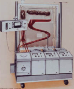
The following is probably the most iconic and important machine and oxygenator configuration ever produced and used. Not because of its elegance or its engineering but because it was responsible for the implementation of open heart surgery with cardiopulmonary bypass worldwide. I am of course referring to the Lillehei-DeWall machine and oxygenator, another “stand-up and run” machine.
The bubble oxygenator, above left on top of the trolley, was made from three lengths of tubing – the vertical bubble column, slanting defoaming chamber and helix arterial reservoir that was positioned in a water bath. These tubing lengths were disposable and new lengths were used for each perfusion. Venous drainage was by gravity into a reservoir chamber from which a Sigmamotor pump pumped the blood to the bottom of the bubble column. Suction was vacuum assisted into a separate reservoir chamber positioned close to the floor. A second Sigmamotor pump transferred this blood to the bottom of the bubble column into which oxygen bubbles were introduced. The oxygenated blood then passed into the defoaming section and helix arterial reservoir where a third Sigmamotor pump transferred the arterialized blood to the patient. The first clinicals at the University of Minnesota were done in 1956. The oxygenator was further developed into a disposable, pre-sterilized sheet oxygenator which became available from Travenol Laboratories in 1957. At about the same time a machine with some of the earliest modular pumps was produced by Sarns in Ann Arbor.
So far so good. We can conclude that, with the exception of the Polystan machine from 1957, modular pumps first became available and in use on pump bases with the introduction of disposable commercial bubble oxygenators. At the same time gravity venous drainage became the standard,with the disposable bubblers having their venous inlets close to floor level. It’s interesting to note that between about 1960 and 1980 an estimated 25 to 30 commercial, disposable, pre-sterilized bubble oxygenators became available, all of which had venous inlets close to floor level. I forgot to mention that with these commercial bubblers, a separate cardiotomy reservoir was needed into which suction blood was pumped before leaving by gravity to the bubble column. This reservoir was usually positioned a little higher than the bubbler.
With todays almost total use worldwide of membrane oxygenators with integrated venous/cardiotomy reservoirs, there seems to be no need for large patient /reservoir drainage heights.especially as VAVD solutions are available. In my opinon there are many clinical and practical advantages in positioning reservoirs both higher and closer to the table. To take full advantage of this possibility all pumps need to be positioned higher and correctly in relation to their function. This is particularly true for sucker pumps as suction is known to be the main source of blood trauma during CPB.
So, I ask you all why aren’t more machine produced and used with multi-positional pumps ? Why does industry continue building conventional machines with “3/4/5 in a row” modular pumps on a base.? Why do todays perfusionists continue to accept this configuration?
NOTE: Some of the images used in this blog, are from my presentation given to the American Academy of Cardiovascular Perfusion (theaacp.com) meeting in Savannah on February 6 this year.
Colin G. Green, Copenhagen, Denmark. ([email protected])


Sometimes simple and concise wins out!
Couldn’t agree more. Over time CPB and the necessary circuitry has become more complex with all the inherent risks complexity brings. As an example, In the “good old days” cardioplegia was a bag of Ringers taken out of the OR fridge, hung up by the anesthesiologist with some additives and infused. Not saying this was ideal but it worked well and patients went home in good shape. Generally I think our surgeons were faster then and our pump times were shorter and this was one of the teams goals – on and off as fast as possible without compromising the surgical quality. It was also interesting to observe that when membranes started to be used routinely, surgeons slowed down somewhat. At least this was my personal observation. Ah well that’s progress.
Fantastic article Colin. I’m certain your presentation at the AACP meeting was a huge success. I have always found the history of perfusion to be very interesting. In my short career I’ve had the opportunity to work with most of the pumps currently on the market. I am not partial to one over the other, but If i had to choose, I like the Stockert S5 Heart Lung Machine.
Thanks Louis and yes, the S5 has some pump positioning flexibility so it provides some choice and possibilities. I wonder how many perfusionists are actively using these possibilities !
The Terumo System 1 also has some pump positioning flexibility but again how many perfusionists are using these possibilities
F.Y.I. When looking through some of my files I remembered that Mera in Japan do a heart-lung machine – the Senko – that has some pump positioning flexibility. You can see an image at: Mera.co.jp
Pretty good thought and very interesting discussion, maybe the future of heart lung machine technology! I think that perfusion as a profession is definitely prone to stagnation and the “this is the way it has always been” mentality.
Thanks Jerry. The blog was written to have some historic interest but also to provoke a discussion. I was part of a team in the mid 80’s that experimentally developed an oxygenator/reservoir and arterial pump that could be hung on the OR table so that venous catheters could be almost plugged in directly to the reservoir and the arterial line was about 60 cm in length as far as I remember. Of course it was voted down by most perfusionists we talked to, perhaps rightly at the time but the concept was good. We also developed an automatic gas controller that, with the help of an in-line pO2 sensor, allowed an ApO2 to be chosen, set and maintained automatically. This was also voted out – “taking away our job”.
Excellent article Colin!
Didn’t Pemco also make a heart-lung machine where all of the pumps were in a vertical arrangement?
Interestingly, I’ve trended more toward standing than sitting for pumping cases, works better to my case flow.
I think the concept of a modular heart-lung machine is a great idea, and has been embraced by a number of pediatric perfusionists, but I feel the “traditionalists” are not ready for this, and the majority is what drives manufacturing.
They did indeed Vince. I think it was short lived. A French company, Collin Gentile Drapier, did a machine in the early 70’s with the arterial module on the base and the sucker modules at OR table height. In my opinion sucker and probably cardioplegia pumps at table height are an optimal solution.
….and as another related comment, Mera in Japan do the HAS II machine with multi- positional pole and horizontal mounted pumps allowing some to be mounted at OR table or any chosen height. Whilst it’s a big and busy machine, there are lots if sensible features and functions. I am not sure of its regulatory status but believe it has neither a U.S. Marketing approval or CE Mark. My apologies to Mera if I’m mistaken. An English language brochure can be downloaded on Mera.co.jp.
Heart-Lung machines are, indeed, changing. I disagree that “the majority” will determine what is used. Those that embrace cutting-edge technology will be followed in time by “the majority”, simply because: you don’t know what you don’t know, until someone leads the way.
It requires a manufacturer to “lead the way”. I would like to see an HLM which can be used outside Asia where sucker pump modules, and perhaps a cardioplegia pump module, can be positioned at or about table level together with an arterial pump that can be height adjustable. I’d also like to see a base unit that incorporates both a battery back-up and a heater-cooler. The Mera unit from Japan has the pump solutions. “Back to the future “
Spectrum Medical is developing just such a set-up, but, doesn’t have the Heater-Cooler in the base. Trying to keep it more portable for those times when heating/cooling isn’t needed for a while. How does 4 hours of battery time sound?
Sounds interesting. I saw an image a few months ago of the machine with the pumps on a curved front arm. It was from an exhibition somewhere. I couldn’t really understand the advantages. Sounds like some further development/thinking has taken place. Look forward with interest to see the end result. 4 hours battery time sounds really good but perhaps an overkill. The heater-cooler thing is wishful thinking from my side but in my opinion still a logical thought. I was in a group in the 1980’s that sketched up some forward thinking ideas. They were based on having a dedicated CPB operating table with incorporated pumps and an oxygenator mounted on the side and a heater-cooler in the pedestal. We ran this idea by a few surgeons and lerfusionists and it was thumbed down. Thanks for your comments.
Just seen an image of the Spectrum machine that was exhibited at the recent AmSECT meeting. Looks very good. Very happy they have done this. The only minor problem I have with remote heads – not specific to Spectrum – is that the controls and displays are placed remotely from the heads. I don’t know how much of an issue this is but perfusionists are used to having controls and displays at the pump head so that they can directly feel and see what they are doing and what is happening with each individual head. I guess it is just something to get used to – not good for the “traditionalists” !!
Colin, we have comforting knobs mounted on the main monitor, and each roller can be assigned a color on the screen readout. The knob controlling that pump is right below the screen readout, and that assigned color is projected onto the pump-head raceway! If you will sit down at the pump and see how it is all so compact, I predict you’ll quickly see how it works well together. We have Perfusionists designing the layout, not just relying upon some Engineer’s ideas of what the layout should be.
Oh, and how about a heater-cooler that has no water in the main system? No more cleaning trying to prevent the current problem? The only fluid that runs through the oxygenator heat exchanger will be part of a disposable. And, I wouldn’t even use water in the disposable part, I’d use normal saline from those one liter screw-cap bottles…probably will take 2 liters. In the unlikely event of a “water-to-blood-leak”, you wouldn’t be killing the patient, either. Since this part interacting with the oxygenator heat exchanger is disposable, no reason to shy away from using saline. At the end of the case, dump the saline in a sink and toss the disposable. We are working on this now…it could be ready by the beginning of next year.
Sounds good. Look forward to hearing more about this. As you say it’s a very relevant direction to be taking. The current HCU contamination issue seems to be accelerating in impact with some potential serious litigation in the pipeline. Not good.
The speed control knob positioning discussion continues to interest me. A couple of weeks ago I gave a talk in Malmö, Sweden. The speaker before me was from Medtronic and he gave a 60 minute presentation of the Spectrum Quantum. I was thus able to see the positioning of the speed control knobs under the monitor. I still think that positioning pump speed controls distant from the pump head could be an obstacle for many perfusionists. With roller pump modules the eyes have only one place to focus when manipulating speed and following a display. With remote pumps there are three places to watch and which are distant from each other – the control knob, display monitor and pump head. This is a significant change in “culture”. I may be placing too much importance on this. Time will tell.
Hey Colin
I’m just now getting a look at your article
I had that pleasure of running one of, if not the first, metronic resting heart
It was , in my opinion, far easier run. In addition to the configuration, it was easy to move if you had to change rooms. ALSO, ath the priming volume was low and we used RAP, and the confuguration elliminated hemoconcentration Completely. The biggest advantage was that at the end of the pump run we could u n-RAP the pump. That is come off pump and transfuse all the pump blood into the parent
The pump remained primed with clear fluid. And we usually only returned 125cc of cell saver
Not sure we’re RESTING HEART stands now . But cost seemed to be the limiting factor
Joe
Hi, I have been following this blog for awhile now and am interested in applying for a cardiovascular perfusion program. I was wondering if there were any perfusionists that were willing to allow me to shadow them or even just interview them. I don’t know a single perfusionist!? It would be great to connect with one (or a few:) before going through the application process. I would appreciate any help or advice on this!:)
Colin, I completely agree with and respect your concerns re: control knob position in relation to the pump. (By the way, the speed control knob console can be mounted anywhere…doesn’t have to be under the monitor) Anything I can offer in words, does not replace actually sitting down and operating the machine. The layout is so compact, the sight-lines are uncluttered, and the color-keyed controller/screen/pump relationships are so obvious, it’s much easier to use than to describe. I see Perfusionists that almost immediately begin to use the side of their thumb to make small changes to rpms, and with almost imperceptible, to completely no need for direct visual spotting of where they reach to make the change. I think it’s not only the matching colors, it’s simple memory of where the knob is in space relative to what they are focused upon (such as the turning pump head). It reminds me of an old cereal commercial, “try it, you’ll like it!” Best regards, Scott